
23i: Mounting the Sensor
 Learning Target
- Understand the role of an accelerometer and gyroscope
- Identify an optimal location for the V5 Inertial Sensor
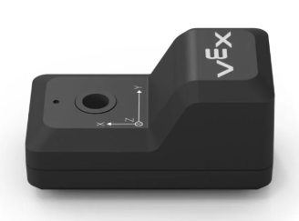
 Inertial Sensor
The V5 Inertial Sensor is both a 3-axis accelerometer and a 3-axis gyroscope.
- An accelerometer detects the forces resulting from acceleration - how fast something is speeding up or slowing down
- A gyroscope detects angular velocity - how fast something is turning and the direction it is turning
You should mount the V5 Inertial Sensor horizontal with the ground. That is how the V5 coding system will expect it to be mounted.

 Instructions
Step 1: Choose a location
Look for a spot near the middle of the robot’s base, between the left and right sides of the chassis.
If it is mounted too far from the center, the sensor may feel extra motion or vibration that does not represent the robot's actual motion.
Always avoid mounting the sensor:
- On the claw
- On the arm
- On any flexible or
- On a flexible or wobbly part
- Too far forward, backward, left, or right
Step 2: Add a mount
Since there is no good flat place to mount the sensor on the Clawbot chassis, use a short VEX steel bar to create one.
You can create a sensor mount at one of the locations shown below in red:
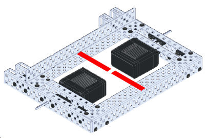
You can use one of the cut lengths from the bin if there isn't one already in your kit.
The bar should:
- Bridge between two solid frame locations -or- be short enough not to vibrate
- Be mounted tightly with at least 2 screws
- Not stick out into the wheels, gears, arm, or claw
- Hold the sensor near the center of the robot
Step 2: Attach the sensor
Mount the sensor using a screw and nut.
Make sure:
- The sensor is flat and secure
- It does not wiggle
- The cable port is reachable
- The cable does not get pinched or pulled
- The sensor is not mounted to a moving part
Step 3: Check clearance
After mounting, test the robot by hand.
Slowly move:
- The arm up and down
- The claw open and closed
- The wheels
- Any gears near the sensor
Nothing should hit the sensor, screws, nuts, wire, or mounting bar.
Step 4: Secure the cable
Plug the sensor into the V5 Brain using a smart cable.
Route the cable so it:
- Does not touch gears
- Does not wrap around shafts
- Does not get pulled tight when the arm moves
- Does not hang down near the wheels
Use gentle bends. Do not sharply kink the cable. Use zip ties to hold it if needed.
Step 5: Final Check
Your team should be able to answer YES to all of the following questions:
- Is the sensor mounted close to the center of the robot?
- Is the steel bar mounted with 2 or more screws?
- Is the sensor attached to a non-moving part?
- Is the sensor firmly mounted?
- Can the arm move fully without hitting it?
- Are all gears and wheels clear?
- Is the cable safely routed?